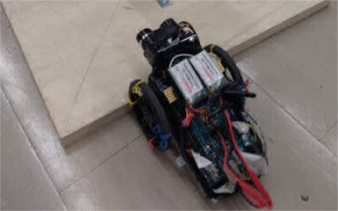
Lane keeping generally consists of lane detection, in which the road lane markings and boundaries are detected, and lane following, in which the vehicle is controlled to stay within the lane markings and boundaries while driving. With a highly accurate GPS and IMU system such as an RTK or DGPS system fused with an accurate IMU, it is possible to follow a prior path so that the vehicle can drive autonomously while keeping itself in a lane. However, the real world is dynamic and it is not always possible to follow a pre defined path. Moreover, these highly accurate navigation systems are expensive and not suitable for implementation in an affordable solution. Therefore, other sensors, such as a monocular camera, are often used for lane detection. In my work, I used a monocular camera alongside a navigation system for lane keeping. The navigation system serves as a fall back solution when situations arise where the lane cannot be detected, yet augmenting the navigation system with a vision system allows for the accuracy requirements from the GPS and IMU to be significantly reduced, to the extent that cheaper less accurate systems may be used in conjunction with the monocular camera.
The first step in a complete lane detection pipeline, after the standard distortion correction, is filtering of the raw image to remove lighting affects that can occur in a normal driving situation. The sun is the main cause of such undesired artifacts on the image and effects such as lens flares and bright rays of light on the image can be detrimental to accurate lane detection. Moreover, it is common for the image to have areas of non uniform light intensity caused by shadows from nearby infrastructure. Although software filtering can be applied to correct these effects, it is chosen to address them physically for simplicity and speed in implementation. This is done by blocking the top half of the lens to remove the sky from the image and by dynamically adjusting the exposure of the camera so that the resulting image has uniform brightness.
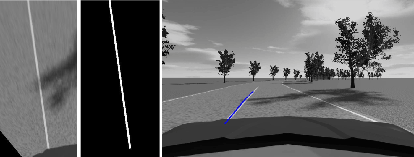
The next step of the lane detection pipeline is the utilization of the camera parameters in order to transform the original image frame into a top-down frame. These parameters include the focal length, principal point, and image size, which are attained from the camera calibration process and also the height and pitch angle of the mounted camera. Initially it is assumed that perturbations in pitch angle of the camera with respect to the road will not cause a significant effect on the lane detection result. As such, the initial pitch angle of the camera is used as a constant input to the transformation. Testing on real world roads may prove this assumption false, in which case the transformation will also implement dynamic pitch compensation. In the front facing image, parallel lane markings appear to converge at the horizon due to the perspective of the image. If the image perspective is transformed to the top-down view referred to as birds eye view, this perspective effect is removed and parallel lane markings are once again parallel. The birds eye view image is computed based on a rectangular sub section of the original image that can be arbitrarily defined. The idea is to utilize only the relevant area around the expected location of the lane marking for lane detection so as to reduce the processing times and any undesired objects in the processed image. The birds eye view image is produced using the inverse perspective mapping algorithm.
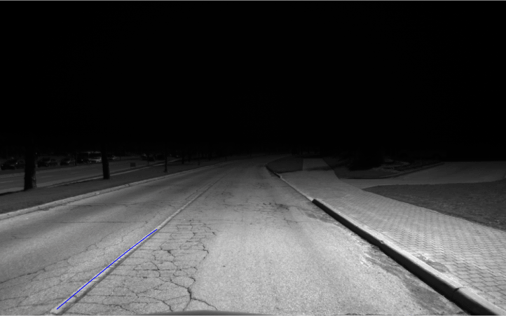
The next step of the pipeline is to identify the lane markings from the rest of the image. In summary, the algorithm takes as input the approximate expected width of the lane marking and finds the markings in the image by searching for groups of pixels that have a high intensity contrast from the surrounding pixels and are near the specified width. Internally, this is achieve through a filter that expects a marking to have low intensity pixels neighboring it. Furthermore, the sensitivity to the lane markings can be controlled via a parameter. Any number of different lane markings detected by the algorithm can be utilized and the algorithm works just as well for a multi lane highway as it does for the single lane marking example shown.
Next, parabolic or cubic lane models can be fit to the segmented lane markings which essentially fit the respective curves to the points making up the lane markings. A RANSAC based method is used for robust curve fitting. The parameters for the model are returned in the original camera coordinate frame.
The lane keeping controller is largely based on the controller used by the DARPA Grand Challenge winning robot: Stanley. The control law uses the lateral error and the heading error as the error metrics trying to be brought to zero. The desired steering angle is linearly proportional to the heading error with a gain and is non-linearly proportional to the lateral error with another gain, and the vehicle speed. When the lateral error is large or the vehicle speed is slow, the desired steering response is stronger. On the other hand, if the lateral error is small or the vehicle speed is fast, the desired steering response is weaker. These help to strike a balance between controller stability and speed of convergence. The image belows shows how the error metrics are derived using the GPS and IMU sytem vs. the vision system. In the combined system, the heading metric is used from the GPS and the lateral metric is used from the vision system.

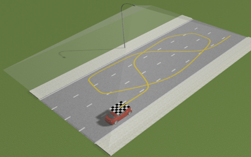
The results of only the GPS based controller and the combined controller are shown below. It can be observed that the lateral error from the path is within 25 cm and the vehicle drove around 2.5 km on the University of Waterloo Ring Road with autonomous steering.

Connect With Me